What This Document Is
This is a detailed specification sheet for the DM74LS367A, a hex 3-STATE buffer/bus driver integrated circuit. It’s a technical resource providing comprehensive information for engineers and students working with digital logic and signal transmission. The document originates from Fairchild Semiconductor, a well-known manufacturer of electronic components, and represents a revision from 2000 based on original work from 1986. It’s a foundational resource for understanding the characteristics and application of this specific IC.
Why This Document Matters
This specification is crucial for anyone designing, building, or troubleshooting digital systems that require signal buffering and driving capabilities. Students in embedded systems design, digital electronics, or computer engineering courses will find this invaluable when selecting components for projects or analyzing existing circuits. Professionals involved in hardware development, testing, or maintenance will also rely on this information to ensure proper system functionality and compatibility. Understanding the nuances of this component is key to reliable data transmission within a larger system.
Common Limitations or Challenges
This document focuses *solely* on the DM74LS367A. It does not provide broader tutorials on buffer/driver concepts, bus architectures, or general digital design principles. It assumes a foundational understanding of electronics and digital logic. While it details electrical characteristics, it doesn’t include example circuit designs or application notes demonstrating practical implementation. It also doesn’t cover alternative components or comparative analysis with other buffer/driver ICs.
What This Document Provides
* Absolute Maximum Ratings – defining safe operating limits for the IC.
* Recommended Operating Conditions – specifying ideal parameters for optimal performance.
* Electrical Characteristics – detailing voltage and current behaviors under various conditions.
* Switching Characteristics – outlining timing parameters like propagation delay.
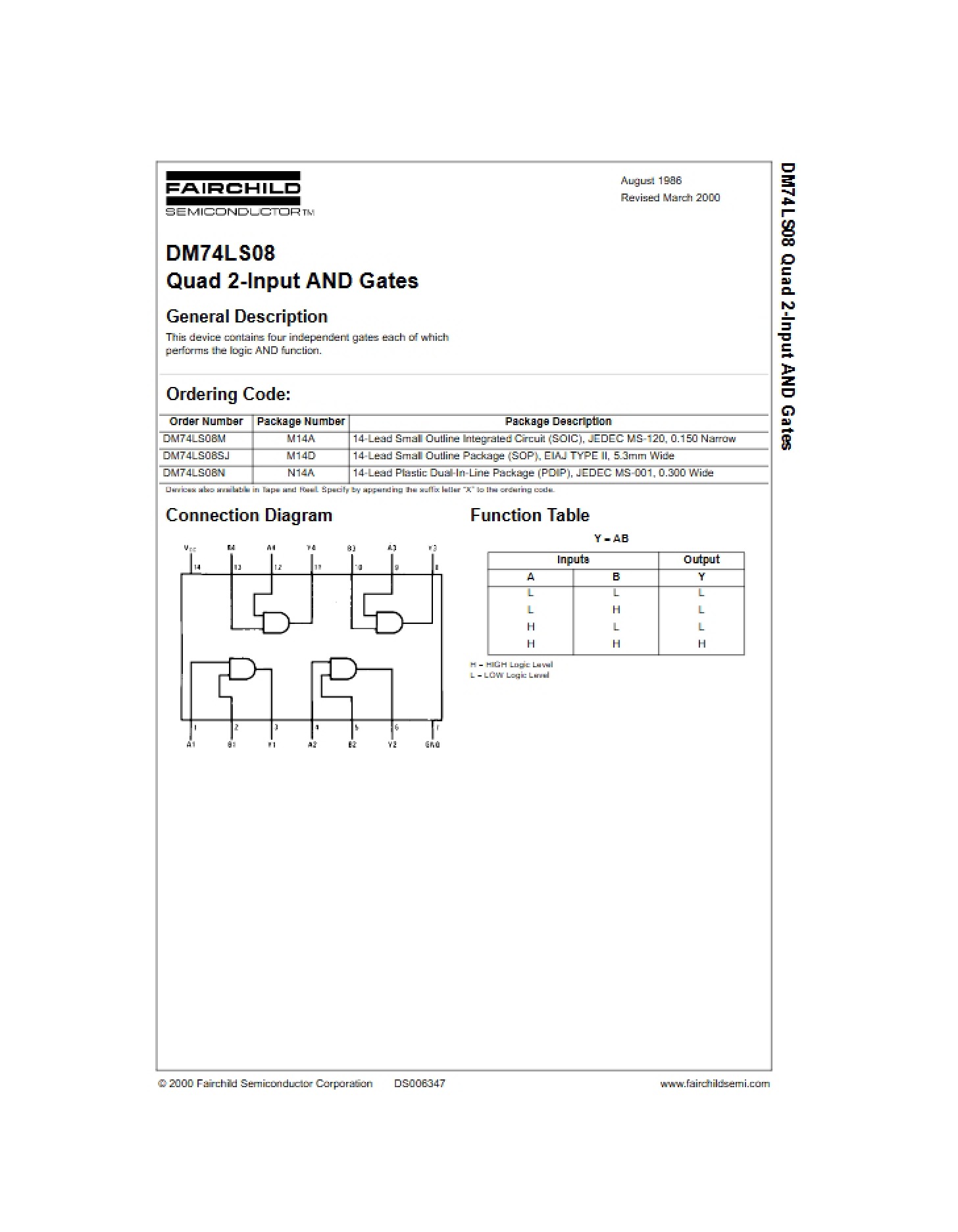
* Function Table – illustrating the logical operation of the buffer gates.
* Connection Diagram – visually representing the pin configuration.
* Physical Dimensions – providing package details for both SOIC and PDIP formats.
* Detailed notes regarding testing conditions and limitations of the provided data.