What This Document Is
This is a detailed specification sheet for the DM74LS257B, a component commonly used in digital logic and embedded systems design. It’s a technical datasheet originating from Fairchild Semiconductor (now Onsemi), providing comprehensive information for engineers and students working with this specific integrated circuit. The document outlines the electrical and physical characteristics necessary for proper implementation in electronic designs. It falls into the category of component-level documentation essential for hardware development.
Why This Document Matters
This specification is crucial for anyone designing, building, or troubleshooting circuits that utilize the DM74LS257B. Students in embedded systems courses, particularly those focusing on hardware interfacing and digital logic design, will find this document invaluable. Professionals involved in electronics engineering, circuit board design, and system integration will also rely on this information to ensure compatibility and optimal performance. Understanding the parameters detailed within allows for informed component selection and reliable system operation. It’s particularly useful during the build and testing phases of a project.
Common Limitations or Challenges
This document focuses *solely* on the DM74LS257B component itself. It does not provide application examples, circuit diagrams demonstrating its use, or guidance on broader system-level design. It assumes a foundational understanding of digital logic principles and electronic component terminology. While it details performance characteristics, it doesn’t offer troubleshooting steps for specific circuit failures or comparisons to alternative components. It is a reference document, not a tutorial.
What This Document Provides
* Absolute maximum ratings for safe operation.
* Recommended operating conditions for optimal performance.
* Detailed DC electrical characteristics, outlining voltage and current parameters.
* Switching characteristics, defining signal propagation delays.
* Logic diagrams illustrating the internal functionality.
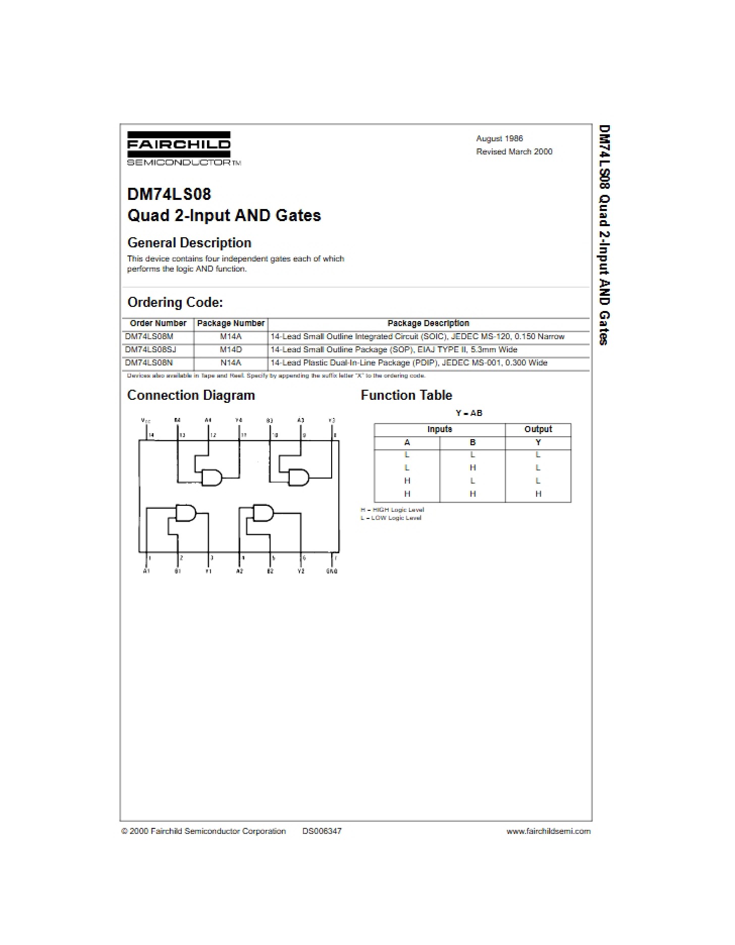
* Connection diagrams showing pin assignments.
* Physical dimension details for both SOIC and PDIP packages.
* Information regarding package types and ordering codes.
* A function table describing the component’s logical behavior.